
After losing Issue 58’s Comms in the post PAUL EVANS now finds BT have ‘accidentally’ disconnected him....
WELCOME TO another great Comms column (slight exaggeration there — Ed). Apparently it’s survived the post system to get all the way to Ludlow (just), so congratulations to the Post Office. As for BT — I hope everyone gets Mercury poisoning, at least until they fix my modem. Due to said problems I’ve therefore decided to have a look at some DIY. It’s basically a reset switch which, when fitted, will prevent the VTX from taking control from the computer ROM when you power-up, leaving you free to program, word-process, or play games! On the touch of the switch, the VTX will boot-up and start the terminal software. This could save a lot of messing around with the peripheral port. The project itself is very easy, involving a bit of soldering and track cutting. The ingredients are one ‘push-to-make-contact’ switch and one N1001 Diode.
EDITOR’S WARNING!: according to Paul all details have been tested with success, but neither he nor CRASH hold any responsibility for this modification. If you really want to proceed be warned it’s purely AT YOUR OWN RISK — it will INVALIDATE ANY GUARANTEES you have!
First, disconnect all connections from the modem (note: this is VTX 5000 ONLY), tip it upside-down and place it on an even surface. There are four screw-terminals at each corner of the case, unscrew these, remove screws and without lifting the bottom off, tip case back up. Now carefully lift top off. Position case with front panel facing you and lift out back silver plate, just to make life easier.
The internals comprise two boards with a ribbon cable between them. The brown board is the actual modem whilst the green is the interface board. We’re only interested in the green area, so leave the brown board untouched.
Unscrew the four terminals on each corner of the green board. Be very careful as the ribbon cable is very fragile. Slowly turn over board, swinging it by ribbon cable, until it’s upside-down and on top of the brown board.
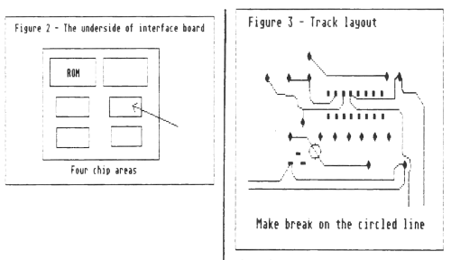
Look at figures 2 and 3. Fig. 2 shows where the area we need to work on is. Fig. 3 shows what we’re going to do. Find the marked track in the diagram on board. When you’re sure it’s the right one, cut it as shown, using the edge of a screwdriver or knife. Be very careful not to damage other tracks. Do not rush. Make sure the track is completely broken so that there’s no way the current could get through.
When you’re satisfied, clear away debris and tip the board upright again, being careful of the cable. Rescrew it and make sure it’s steady. Now heat up the soldering iron. In fig. 4 there are two points marked around the area of the ROM chip (the one with the surface covered by tape). Find XTAL (a large silver object) and slowly bend it upright. The second point should now be easier to access. Next, solder two long-ish wires onto the switch, one for each terminal. Wrap the ends of the wire around the diode pins, one for each side. It doesn’t matter which side you use. Solder them in and make sure they’re secure.
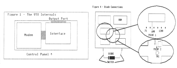
Now get the diode ready and make sure you know where the two points are. Point 1 is by the printed ‘900’ on the board by the small socketed chip, and point 2 is just above TR1. When you’re sure, solder the diode in these two points. The stripe on the diode must be on the left, so that the pin goes into point one, and the other side into point two. The best soldering technique is heating the base of the diode pin and pushing it into the point, which will heat up and let the pin through. Make sure both pins are secure in their new sockets.
It may be a good idea to cover the XTAL with insulating tape, to make sure it doesn’t short on the diode pin. Also, multitest the whole thing so you find out if you have gone wrong BEFORE you power-up. To put in the finishing touch, drill a hole in the front panel and mount the switch there. Re-assemble the entire thing and try it!
If the switch has no effect, check the diode is in correctly, or that the track is scraped off successfully. If you have made a mistake, it is unlikely you have done any damage! Fortunately, as the modification is only to the interface, BT approval will not be affected.